- Announcements
- BBQ and Food
- Cars
- Computing
- Cool Stuff
- Current Events
- Electric Vehicles
- Electronics
- Energy
- Flashahaulism
- Funny
- Government
- Hints and Tips
- History
- HVAC
- Induction heating
- Internet
- Lighting
- Misc
- Neon and other lighting
- Nuclear
- Personal
- Pets
- Philosophy
- Photography
- Power Generation
- Product Reviews
- Projects
- Q and A
- RV/Camping
- Science
- Tellico
Categories
Blogroll
 Print This Post
Mini-Ductor® Induction Heater
PermaLinkReview and Analysis
For the last year I’ve been involved with a start-up called Fluxeon®, a company founded to manufacture and sell low cost induction heaters.
Update 12/30/2020 – I am now retired and no longer associated with Fluxeon. This article represents my personal opinion.
(If you don’t know what an induction heater is, go here) Naturally one should be aware of his competition so we recently decided to take a look at the Induction Innovation’s Mini-Ductor® hand-held induction heater. Going by the specifications, this heater competes head-to-head with our upcoming product, both price and feature-wise.
Another reason that I wanted to take a look at this unit is that I’ve been contacted by several potential customers interested in something that would do a better job. To be fair, their applications are outside the Mini-Ductor® intended area which is automotive-repair-related.
So we purchased a unit and I proceeded to evaluate it, tear it apart and reverse-engineer it (but as will be obvious, not copy it). I decided to write this review to share my opinions with others.
Receiving
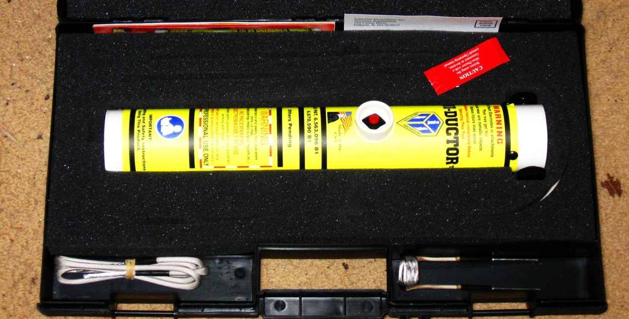
Here is how I received the unit. It is sturdily packaged in a foam lined plastic case. Included in the case are the heater itself, a nut heating coil, a flexible coil made of Litz wire that can be wrapped around things and a single strand wire that can be molded to any shape. Plus the usual warranty card and a fairly lame instruction manual, half of which is taken up by warnings. One can tell that the lawyers are in charge of this company because it has such creative warnings as not to wear anything with metallic buttons or zippers for fear that one might get burned! I kid you not.
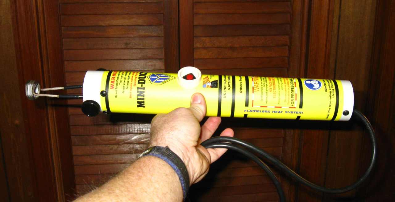
Here’s the unit in my hand with the nut heater coil attached. This unit is much larger than it might appear in brochure pictures.
The body of the unit is a length of thin wall PVC sewer pipe. (OK, I’m just kidding about the sewer part but it IS plumbing tubing). The shroud around the power button is another machined PVC piece that is attached to the main body with cement. The power cord enters the rear through a drain grating inside which a fan resides. On the other end are two “D” shaped pieces of either copper or brass with standard electrical lugs soldered on. These lugs receive the work coils.
The “D”s are held to the PVC pipe with 4 large sheet metal screws. When the unit is on, these screws are “hot” with RF energy. It’s possible to get a little RF burn by touching the hot D with a sweaty finger.
First Test
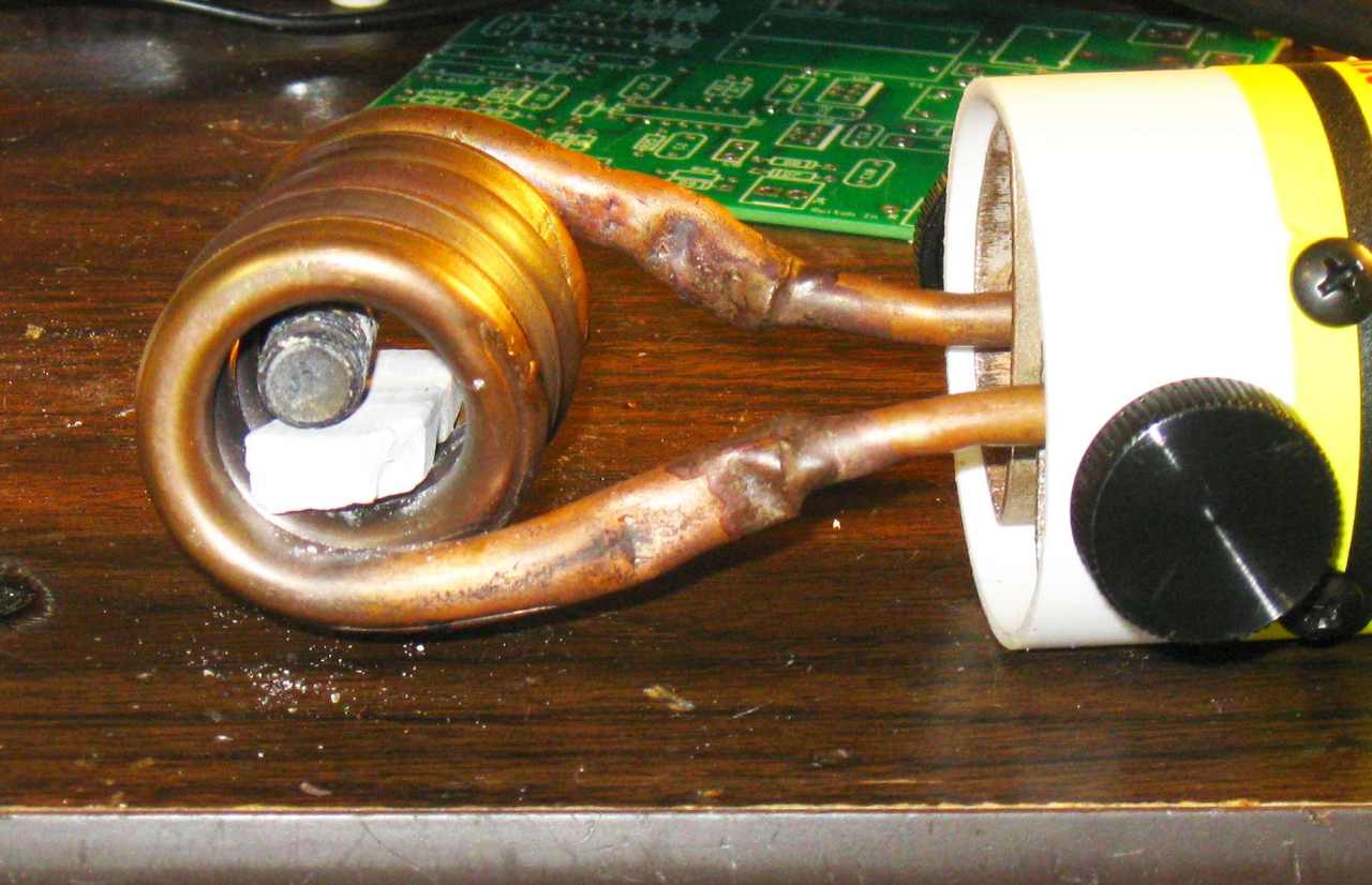
Naturally the first thing one wants to do with an induction heater is to heat something So I cut the head off a half inch bolt and proceeded to heat it.
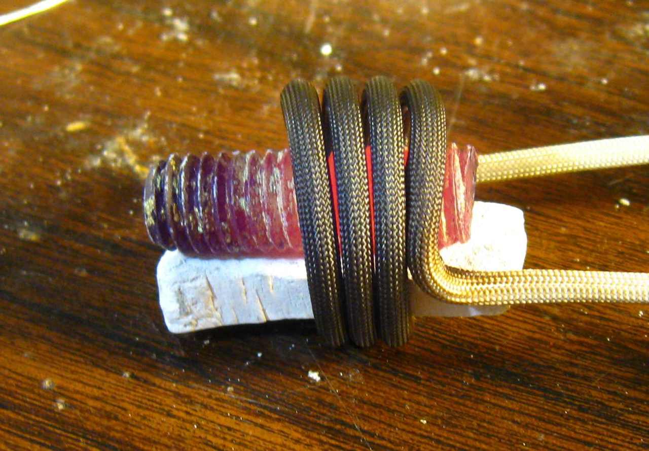 After about 20 seconds this is what I got. Frankly I was not impressed. The company rates the heater at 1000 watts. They don’t specify so I assume that this is input wattage drawn from the power line.
The Fluxeon 1kW induction heater will almost melt this bolt. It heats it to a brilliant white heat with little sparklies coming off. This is NOT a 1kW heater.
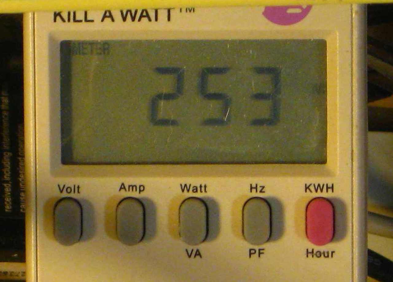
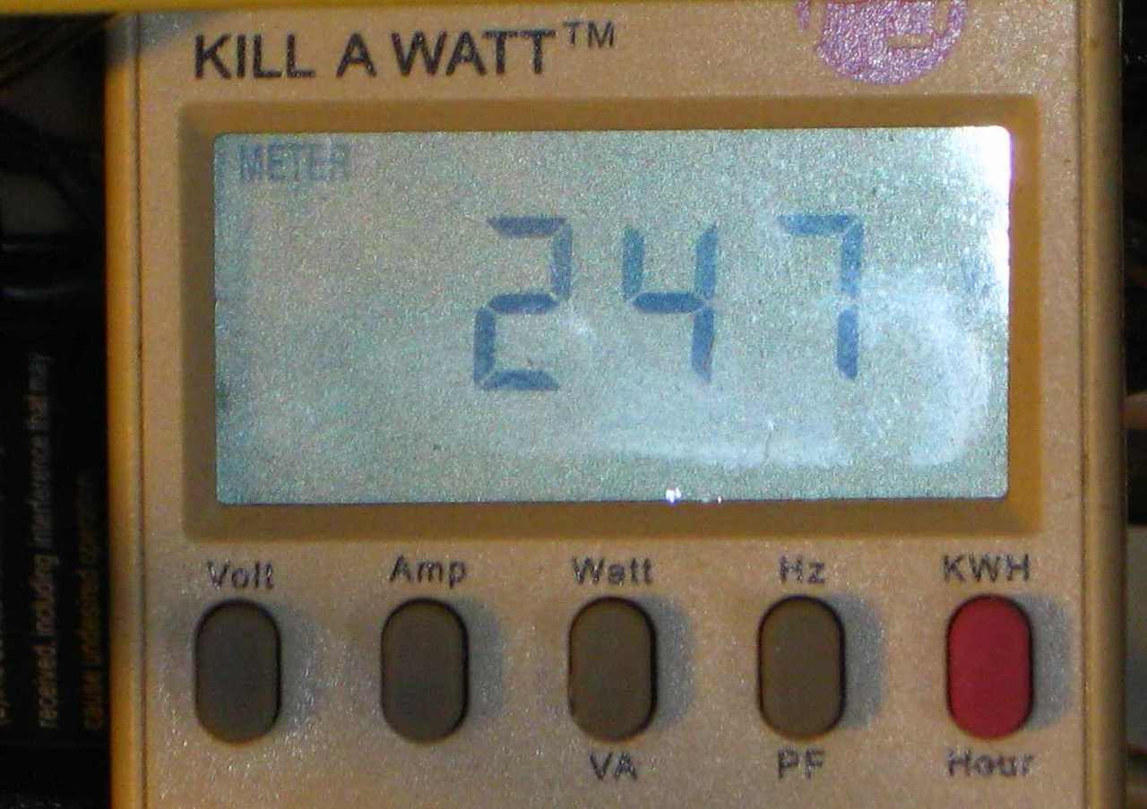
The next step was to see what the heater is really doing. So I got out my trusty old Kill-A-Watt. I have previously compared this meter to lab standard watt meters and found it to be accurate to the watt. So I plugged the Mini-Ductor® into the KAW, placed the bolt back in the coil and…
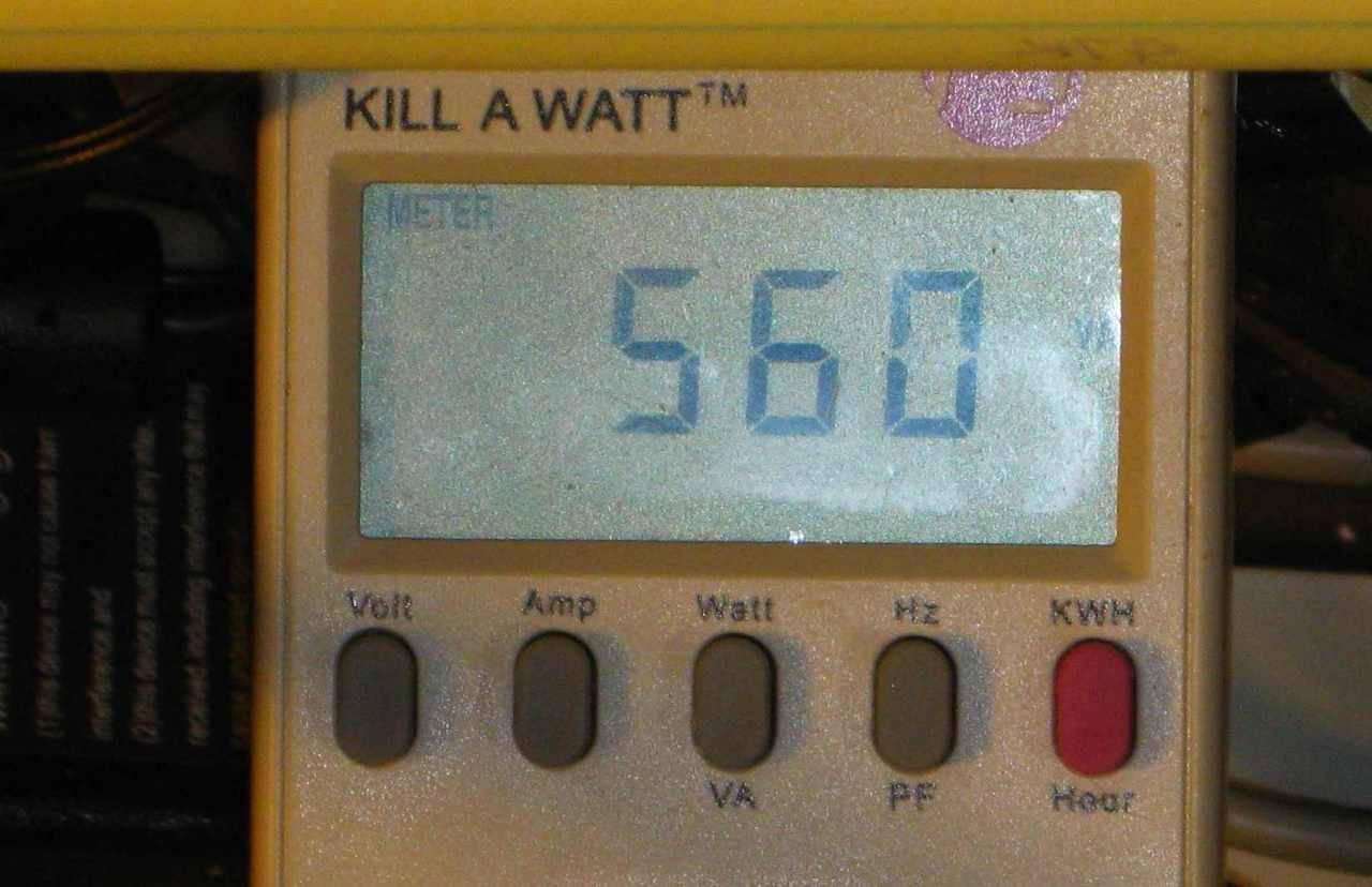
What the KAW read. It only read this value for an instant. After that the power ramped down steadily as the work coil heated up and its resistance increased. It ended up around 400 watts.
Interestingly enough, and just the opposite of the behavior of most induction heaters, this heater actually drops power when the ferrous metal goes through the Curie point. Most heaters, if they don’t have Automatic Power Control increase their power input after the Curie point. This is a function of the electrical architecture of the unit. More on that later.
Seeking Power
Needless to say, I’m was not impressed. So I started looking for that missing power. One obvious limitation would seem to be the work coil. It is made out of tin plated, approx AWG 10 wire. A heavier coil would have less resistive losses and thus should transmit more power.
So I dug out one of the helical coils that I wound for our heater, brazed smaller tubing to it so that it would fit the electrode attachment fittings and tried it out.
Not so good. In fact, just the opposite of what I expected. A possible reason might be that this coil is slightly larger in diameter than the nut heating coil supplied with the Mini-ductor®.
The manual says that the more turns over the work, the more heat is produced. Sounds reasonable so.
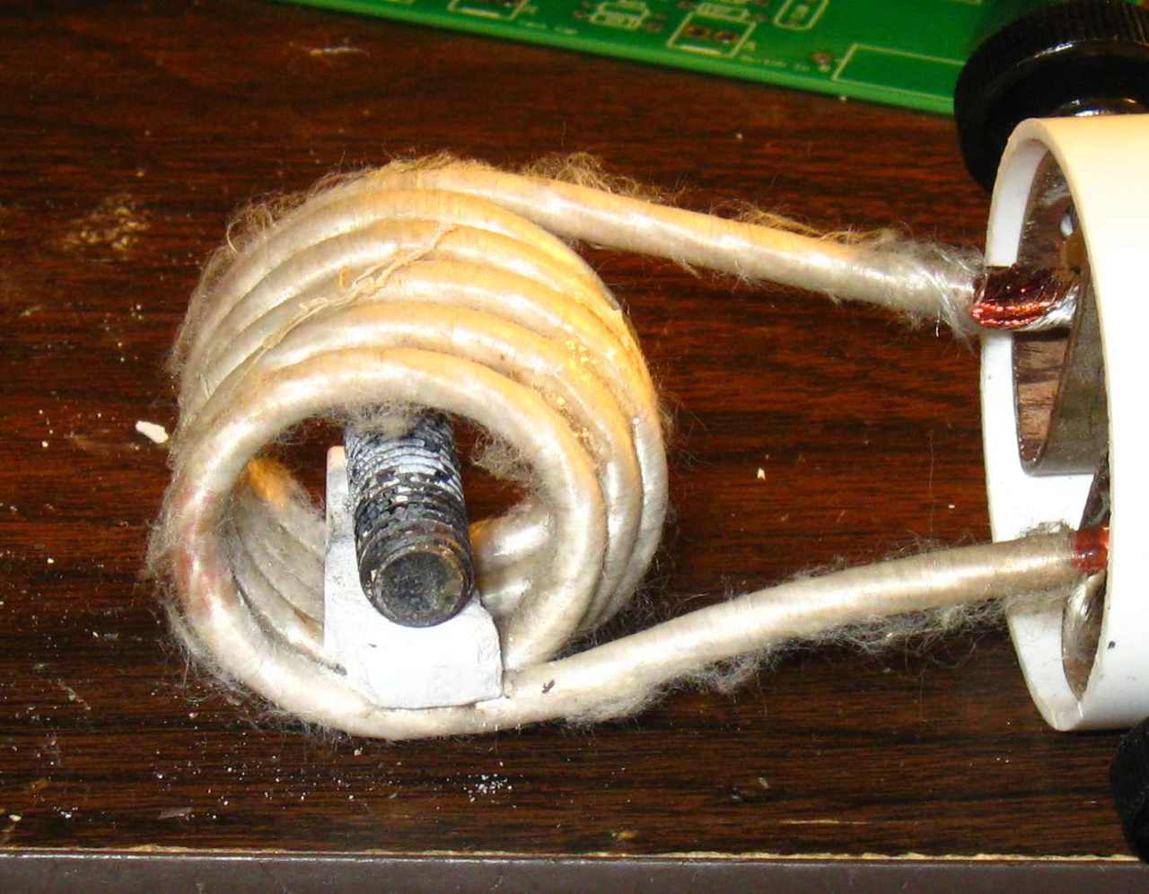
I would a coil out of very heavy gauge Litz wire. I figured that the Litz wire, having lower resistance to RF than regular wire, would give the heater every possible advantage. Unfortunately…
Even worse. Again, part of the problem may be with the diameter of the coil. I didn’t have anything handy to wind a smaller coil onto but based on my work with other heaters including the one that I designed, the minor difference in diameter should not have made much difference. In fact, my heater actually transmits more power to that same bolt with a work coil this size.
At this point, I had to reach the inevitable conclusion that the company is advertising this heater as something it is not. I can’t imagine any way of loading this heater that would cause it to draw a kilowatt from the line. Will it do the job that it’s intended for? Probably, if you’re patient. Is it truth in advertising? Nah.
Peeking Inside
The performance testing out of the way, it was time to look under the covers, so to speak. Opening the unit is trivially easy. Just pop out the 4 screws holding the “Dees” in place, remove and unhook the power switch and shake out the guts. They are not held in place by any fasteners. Just slid into the sewer pipe and roughly affixed by the stiff leads going to the “Dees”.
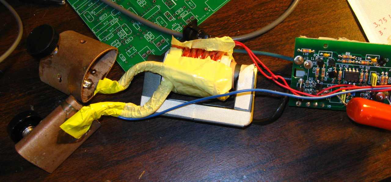
This heater is of the Royer architecture. Here is a view of the business end of the guts. On the left are the two “Dees” that the work coil attached to. In the center is a ferrite-cored transformer and on the right is one end of the printed circuit board (PCB).
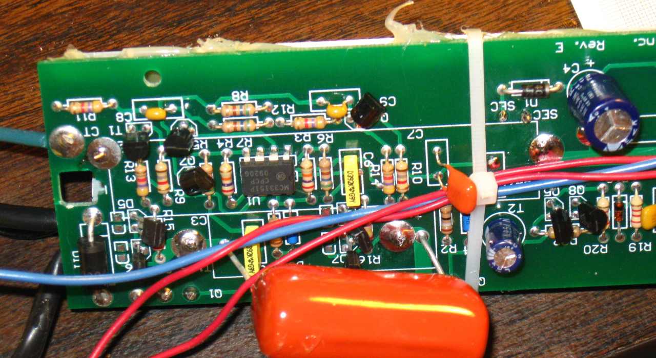
Here are some more views of the PCB. The big orange capacitor is the tuning capacitor that resonates the transformer primary.
Note the highly optimistic 12 amp fuse!

In this view the little cooling fan can also be seen. Interestingly enough the fan is powered by a single loop of wire looping through the transformer core. I imagine that was cheaper than dropping the line voltage down to the 12 volts that the fan requires.
 The architecture of this heater is what is known as a current fed Royer architecture. A functional diagram is shown at the left.
The high voltage DC from the line voltage rectifier comes in at the top and feeds the center tap of the transformer through the current feed choke. Each half of the transformer primary is fed by a power IGBT. When one IGBT is on, the other is off and vice versa. This is known as “push-pull” drive. The resonating capacitor tunes the transformer to the operating frequency and ensured that the transistors always switch at the Zero Crossing Point or Zero Voltage Switching (ZVS).
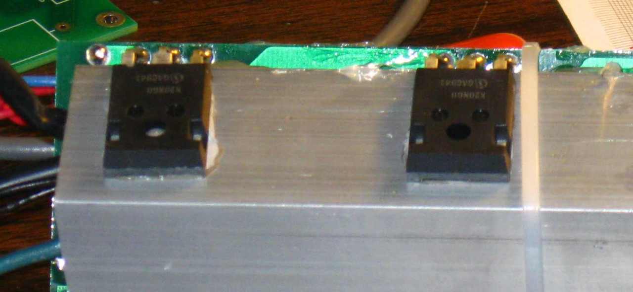
Here are the actual transistors. This is something that I really don’t like. They are simply glued to the aluminum heat sink using a thermally conductive glue. The glue is quite brittle – it easily flakes away at the light touch of a screw driver tip. Thus one could anticipate that these transistors could come unglued, perhaps when the unit is dropped, and subsequently over heat.
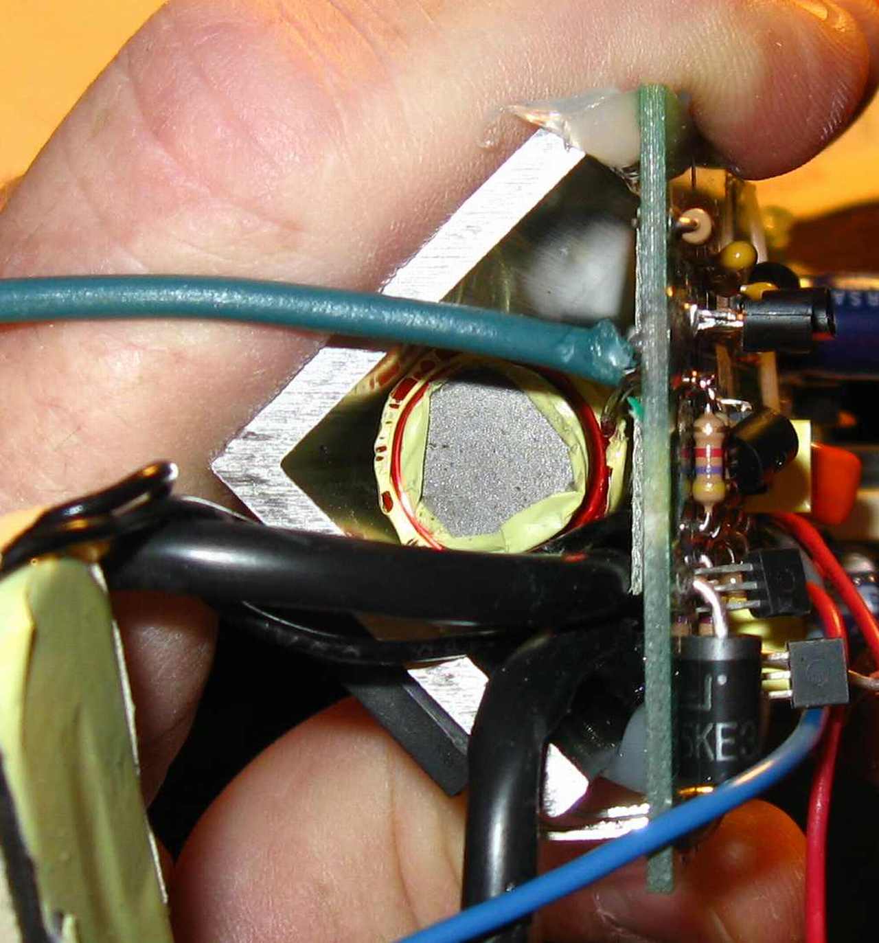
The choke can be seen here, nestled inside the aluminum angle iron heat sink. It is not attached to anything other than by its leads and presumably a little pressure from the angle iron so it is subject to vibrating or being jarred loose.
I can understand the company trying to hit a price point but this use of glue and cable ties to hold the assembly together does not sit well with me. It certainly does not look mechanic-proof
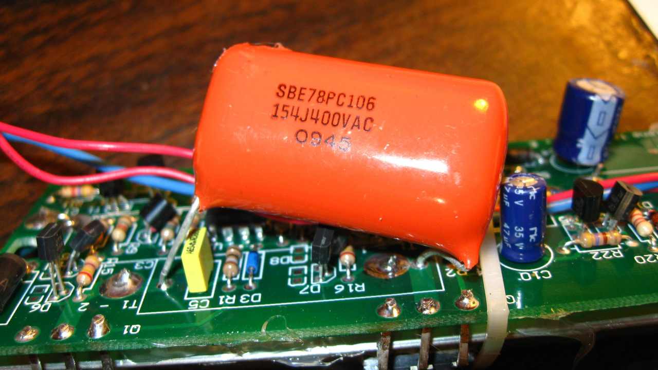
This is the resonating capacitor. It is appropriately sized and rated but again, it’s just hanging by its leads. Not even glued down.
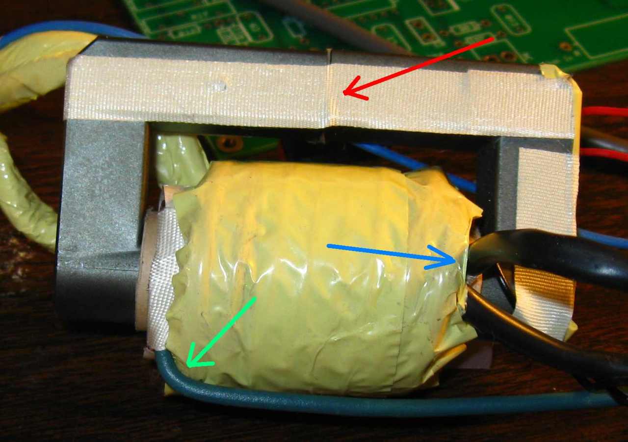
Now to the heart of the unit, the transformer. This photo shows several features. The red arrow shows two things. One, a small air gap to prevent the core from saturating and two, that the two core halves are offset. In fact, this core is held together only by that white tape. It is usual practice to affix the core halves with cement to make sure that they don’t come loose. That wasn’t done here. Just some tape that can loosen with heat and age.
The green arrow shows the center-tap lead entering the primary. The blue arrow shows the two Litz wire primary leads.
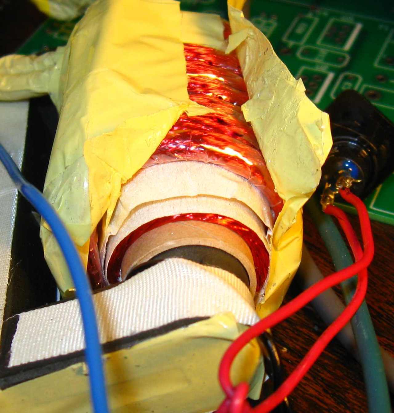
Here is some detail of the transformer with the outer tape peeled back. Pretty standard construction. The primary is next to the core and the secondary is the single layer of heavy Litz wire on top. Under the white tape is the single loop that powers the cooling fan.
Again here, tape is used to hold things together instead of cement or mechanical fittings. Still seems not mechanic-proof.
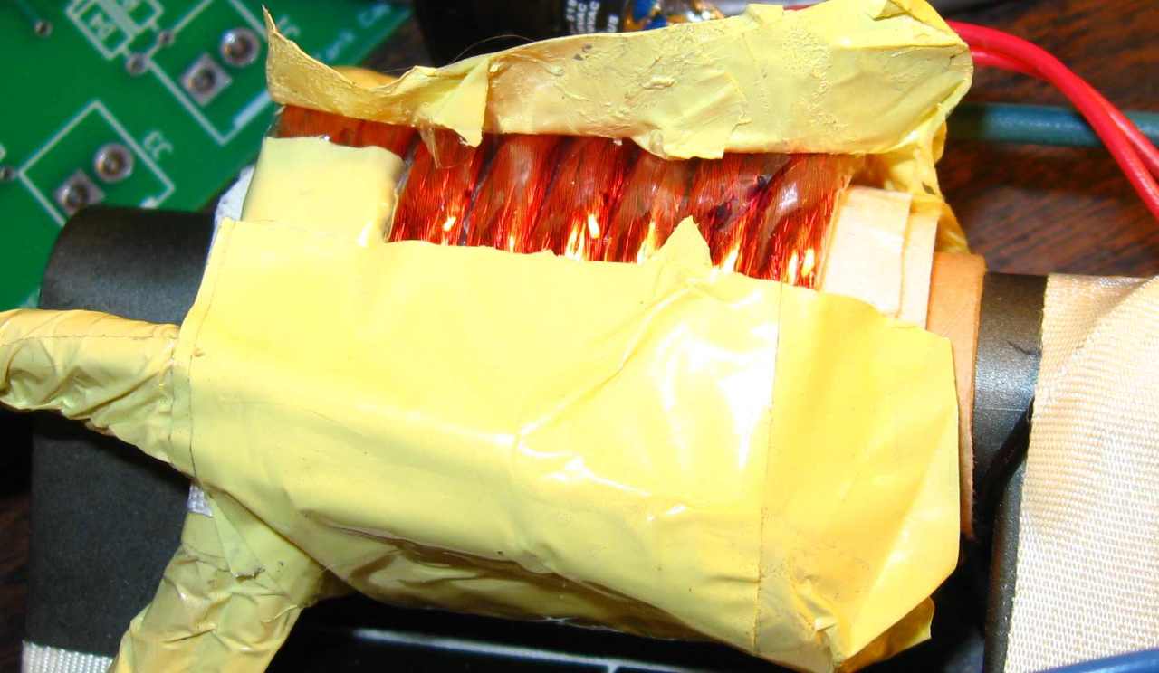
Here’s a look at the secondary. If you look closely you’ll see that the secondary is actually two Litz wires in parallel. There are 5 turns to the secondary.
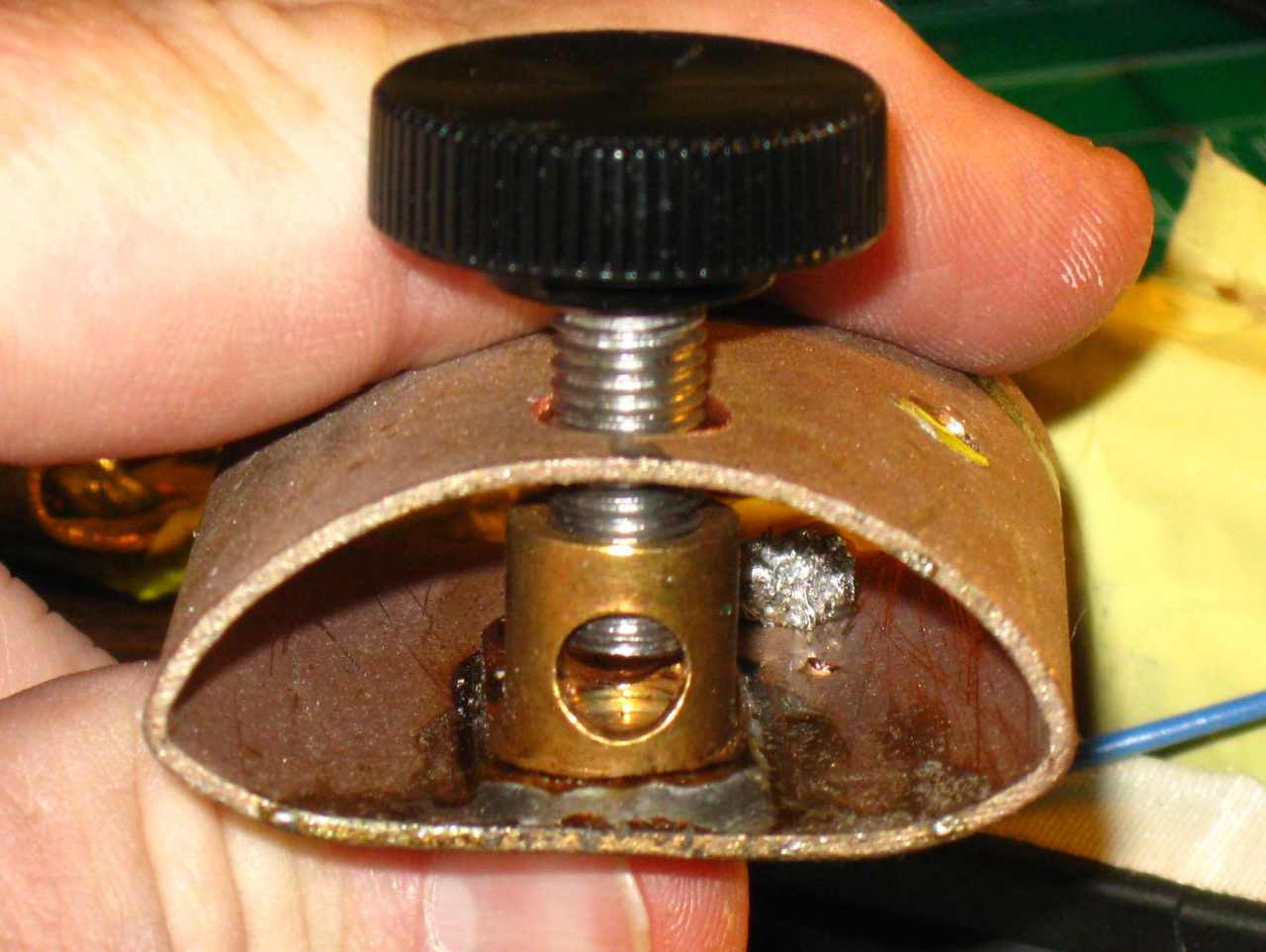
Next we come to the “Dees”, the part of the machine that anchors everything down and receives the work coils.

In this view you can see the Dee itself and the standard electrical lug (red arrow) that is soldered to the Dee. You can also see where the Litz wire is rather sloppily attached to the Dee (green arrow)
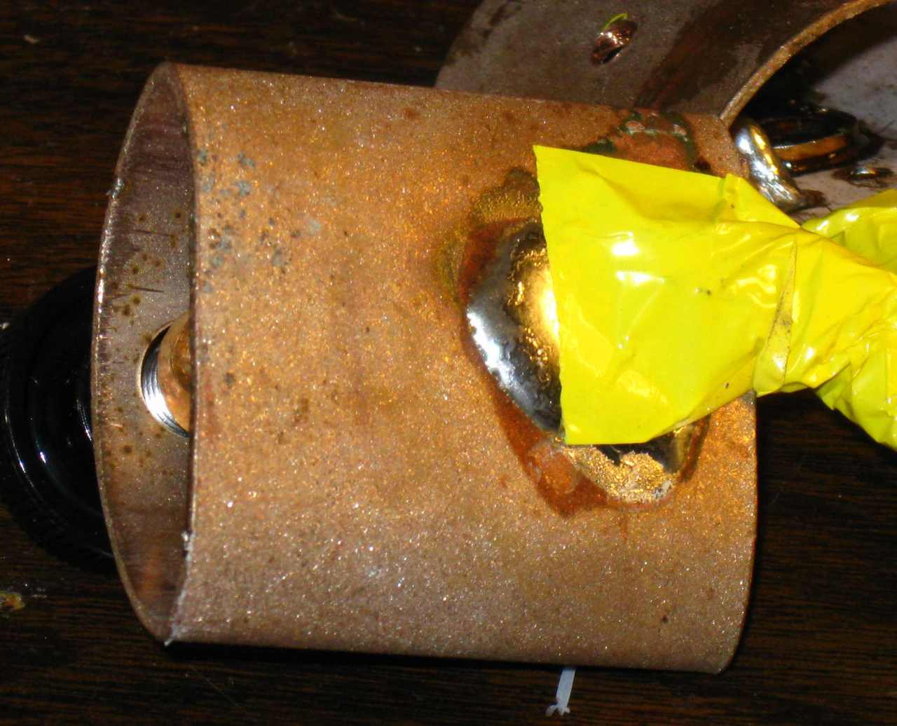 Outer view of the Litz wire attachment. Again, the use of tape where something more substantial would seem appropriate.
Electrical Analysis
The next step in my evaluation was to connect an oscilloscope to the unit and see what I could see.
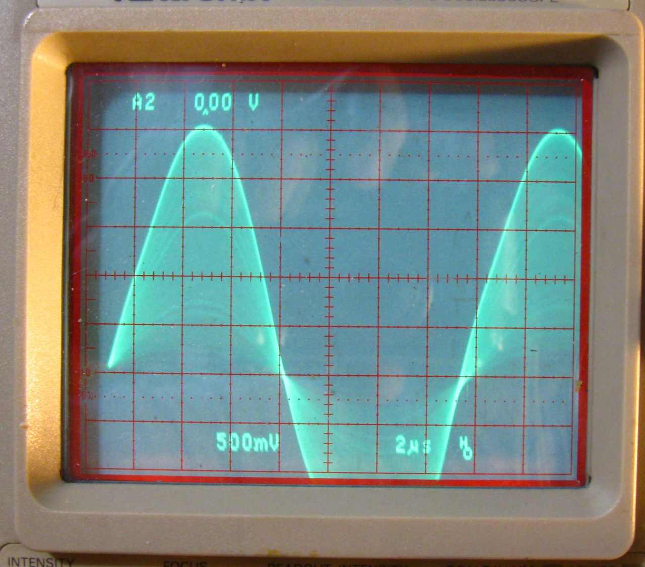
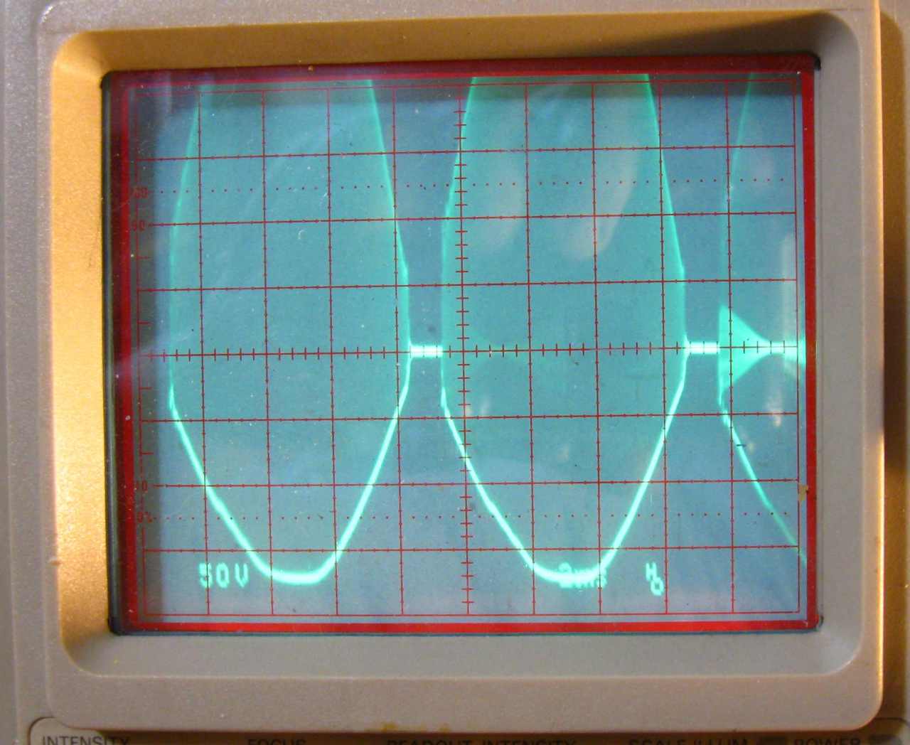
Here is the voltage across the work coil. It is a nice, low distortion sine wave, what I like to see. What I don’t particularly like is the envelope. That is, waves of all different amplitudes, represented by the filled in area under the curves. Let’s see why that is.
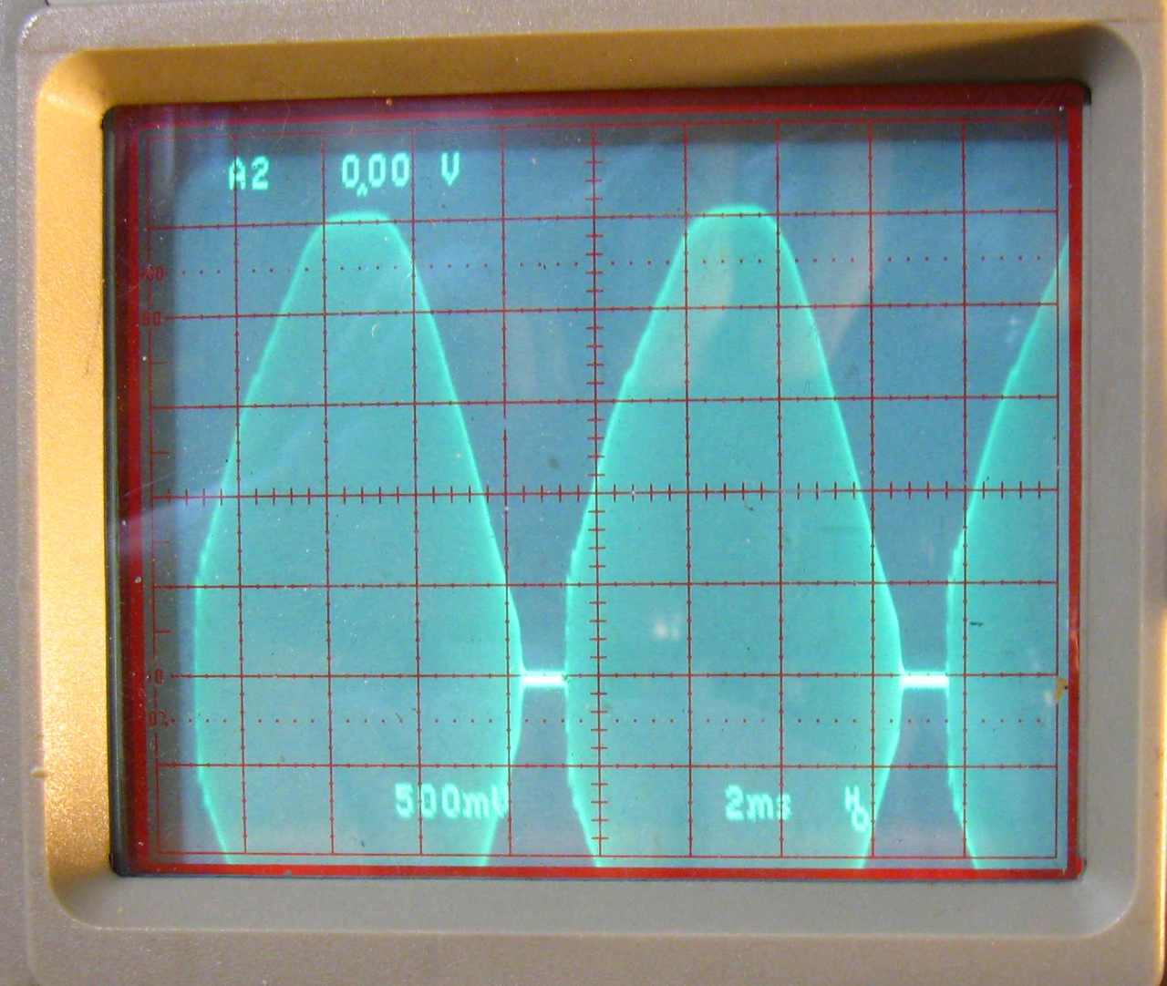
Here is the current waveform with the scope time base turned down enough to see the 120 hz envelope. Each envelope is a half wave of the full wave rectified 60 hz incoming current.
For some reason they chose not to filter the rectified DC. The result is a lot of power opportunity wasted. The peak current in the primary is about 30 amps. If the rectified DC had been filtered even a little, all or part of that un-lit space between the envelopes would be lit. That represents lost power. With good filtering, the screen would be lit solid across the waveform. That would represent the maximum power that could be produced for a given peak current. Perhaps there wasn’t room for a capacitor in the sewer pipe or perhaps an electrolytic cap cost too much. Whatever, this is where some or all of that missing power has gone to. I imagine that the power at the peak of the waveform is at least a kilowatt but the RMS value, what does the heating work, is much less, probably half.

This is the voltagewaveform at the lower side of the current feed choke. Pretty typical for that kind of feed.
Here is the voltage waveform on one of the IGBT’s collector leads. Again you can see the envelope produced from the unfiltered 60 hz power.
Conclusion
The first question on many peoples’ minds is “Is it worth the money?” At about $400 street price, it’s a close call. It will probably do most of the things that it is advertised to do. That is, it will heat stuck nuts and bolts and will work out dents in sheet metal and release adhesive holding things to metal. On the other hand, it is a very cheaply made product that probably will not withstand the rigors of shop use. I can imagine the results of a few drops onto concrete floors, especially in cold weather when the plastic gets brittle.
One thing that this heater is NOT is a general purpose induction heater. As we found out, it can’t heat neon electrodes. In fact, that deficiency is what started us on the Fluxeon path. <shameless plug> The heater that we will be introducing in a couple of months is a general purpose heater. It will initially be rated at 1000 watts but in reality, that is the minimum power that it’s capable of. It will do significantly more in typical situations. Tape and glue will not be structural elements either.
12/30/202 – This review is 10 years old. http://www.fluxeon.com has been in business for about 10 years. This review also probably does not represent what Mini-ductor sells now. I think it’s informational enough to leave up nonetheless.
</shameless plug>.
Stay tuned to this space for updates and occasionally check in on http://www.fluxeon.com.
John
12/30/2020
There is a potential benefit of designing a heater without a filter/rectifier. The most important aspect is that the harmonic power factor is near 1, typically 0.99. That means one could draw 120 volts * 18 amps * 0.99 = 2138 watts. Since this heater can get nowhere near that wattage, this aspect is irrelevant. The tradeoff is that all the time the input voltage is less than peak on each half cycle, the heater makes less output.
The other potential benefit is that there is no stored energy in a filter capacitor which would be enough to blow a transistor if the output were shorted or became open. After I wrote this article, I pulled out one work coil lead while the unit was operating. The heater promptly shorted one IGBT, blew the internal fuse and tripped the 20 amp branch breaker. I replaced the transistor and sold the unit so I didn’t explore this any further.
A rectifier/filter input has a harmonic power factor of about 0.7, depending on the size of the filter capacitor. Thus on a 20 amp branch, one can only draw 120 volts & 18 amp *0.7 = 1512 watts. The unit would be drawing 18 amp and 2160 VA but only 1512 real watts.
My design philosophy for the Roy induction heater was to be able to pull every available watt out of the line so I designed in active power factor correction. Its total power factor is 0.99. I implemented the active PFC in firmware. The reason is that the output of a typical cheap big box generator more closely resembles a distorted triangle wave than a sine wave. This confuses many of the single chip solutions. My firmware takes a look at the incoming waveform for a few cycles before selecting the appropriate algorithm.
I used 18 amps because of according to the NEC, a breaker should trip at over 80% of the nominal rating under continuous load. The breakers in my lab’s subpanel would carry 20 amps continuously but I used the NEC spec to be conservative.
Posted by neonjohn on January 8th, 2010 under Electronics, Induction heating, Science
January 14th, 2010 at 2:29 pm
I also noticed that the PCB uses thru-hole components for all its “jelly-bean” stuff. Whenever I see that now days I think “crap”. It’s not designed for efficient mass production. Who uses thru-hole signal resistors now days?
-Bruce
January 14th, 2010 at 5:14 pm
Well, uh, geez, I guess that I’m guilty of making junk too, cuz I still do thru-hole stuff. I just don’t see the need of going through the torture of debugging a microscopic circuit that is only going to be built in the few hundreds. Thru-hole is big enough for even us old geezers to see – at least with a little magnification.
John
January 15th, 2010 at 2:36 pm
I guess I’ve just become spoiled by working in Silicon Valley for the last 25 years. When you watch a contract assembler literally shoot chip resistors onto a board at 300 per minute. And reworking chip resistors has always seemed easier to me. Instead of using a soldering iron and risking damaging the via/barrel, you just blow a needle jet of hot air onto the chip and simply lift it off. Regarding “microscopic” it doesn’t need to be. You don’t need to use “0201”s or “0402”s. You can use “0805”s or “1206”s “http://www.interfacebus.com/resistor_table.html”.
-Bruce
January 27th, 2010 at 5:09 pm
the posted link is not available John, change it to : http://www.fluxeon.net, else the search will be kicked off (btw on the site I havent found any data that will be usefull)
regards
shad
January 27th, 2010 at 5:37 pm
Shad:
Yeah, we haven’t had time to get fluxeon.com set up. We had to buy the domain from a squatter which took time. fluxeon.net is also really a place-holder until we can get some content up. That’s why I said to “stay tuned” :-)
January 31st, 2010 at 4:23 pm
will stay tuned up :)
also i have some questions regarding to the ind.heater stuff – some weird idea is sneaking in my mind – maybe I should send You via mail the stuff. its related to some home use. as I am not so tight bonded with the technology of it, maybe You can answer the questions. thanx in advance.
regards
Shad
January 31st, 2010 at 4:32 pm
To contact me privately, follow the “contacting me” link at the top of the page. That will take you to a de-spammed email address.
John
March 17th, 2010 at 6:14 am
Dear John,
pleas, write any new versions of devices you have.
Who is responsible for sales of devices?
Notify export prices.
We will buy a device for testing.
If the device works well, then we will buy in bulk.
We can arrange the sale of Russia, Ukrainian, Belarusian and Germany.
Best regards
Michael Semko
May 7th, 2010 at 1:12 am
i have a inductor heater and it has worked well done all the heating jobs ask of it i have 15 kva unit as well it compares well for it size with that unit all i can say is if you can do better why havnt you got one on the market. BILL
December 15th, 2010 at 11:08 pm
dear sir i want to make a induction heating
2kw 100khz can u sugest me circuit
December 20th, 2010 at 4:46 am
dear sir,
please send a purchase information of mini ductor induction heater. also inform a price details
thanks
June 1st, 2011 at 12:57 pm
Does the Kill-a-watt voltage amount stay fairly steady or does it fluctuate quite a bit?
June 18th, 2012 at 7:14 am
If someone gave me that unit with no data whatsoever and asked me to evaluate it, I would say it was an engineering prototype. Certainly not something that would be sold to the public! Whoever designed it has zero experience in production engineering design!
But the basic concept is excellent, a lightweight hand held unit that has satisfactory power. As John was pointing out many places, that unit is not going to last for any length of time.